
SPS (Spark Plasma Sintering) is a sintering technology that combines fast heating and pressure. In this technique, the starting sample is placed in a graphite die and a voltage is applied between the two plungers, resulting in rapid heating by Joule effect. A whole sintering cycle can be completed in less than an hour with minimal grain growth. The technique is highly effective on hard-to-sinter materials.
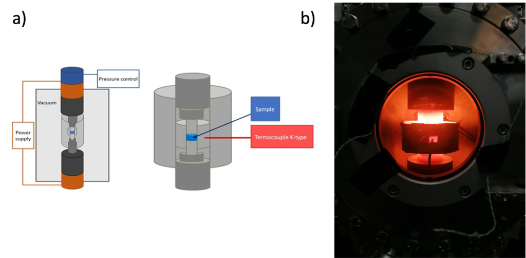
Fig. 1: a) schematic representation of an SPS machine; b) SPS machine during a sintering cycle
Since the heating is generated by the joule effect directly in the sample holder, there are some major limits to the scalability of the technology. Increasing the dimension of the sample means a rapid increase in the current intensities required to reach the desired temperature. At the same time, the control of the temperature homogeneity becomes difficult.
To increase the adoption of SPS technology in the industry, these limits must be addressed. A possible solution is represented by the optimization of the tooling geometry to reduce the required current densities and favor a homogenous heat distribution in the sample. We choose to adopt Ansys software to do so, thanks to its built-in optimization tools.
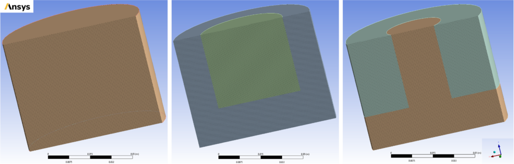
Fig. 2: Example of three different plungers geometry. On the left is a solid block of graphite. The Center and left plunger are made of two different blocks of graphite, one of them being electrically insulated.
At the moment, the main challenge in modeling this technique is represented by the correct evaluation of the electric and thermal contacts at the interface between the parts of the tooling. The first step was to evaluate the contacts in the plane perpendicular to the applied pressure (horizontal). To do so a model tool presenting only horizontal contacts have been used. Its geometry can be seen in the following image.
Fig. 3: Working setup for evaluating horizontal contact. a) actual image of the setup used in the experiment b) Setup in operando c) and d) the same setup reproduced in ANSYS.
Once the study of the horizontal is completed, the next problem will be represented by the sliding contacts parallel to the applied pressure (vertical). In this case, the geometry will be the following.
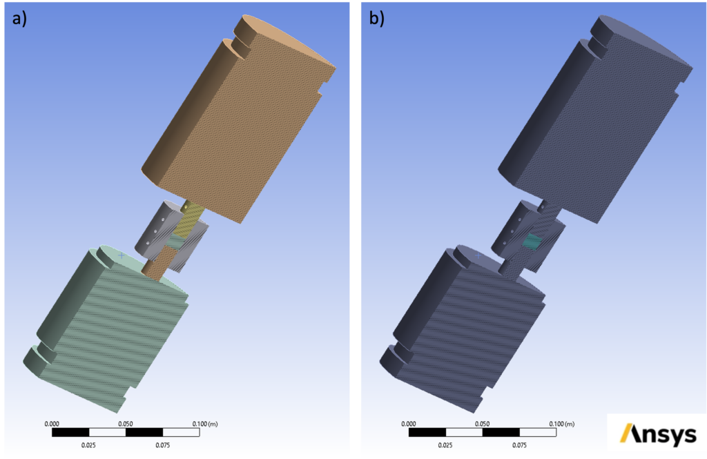
Fig. 4: SPS setup for evaluating Z contacts. a) Setup colored by bodies b) Setup colored by materials.
Once the calibrations will be done, the optimization will be completely focused on changing plungers geometry, like in image 2.
July 25, 2022