
Introduction
Percutaneous Coronary Intervention (PCI) is a well-known minimally-invasive therapeutical option for coronary artery stenosis. Although, several clinical studies have demonstrated the safety and the efficacy of PCI to treat focal and simple lesions, the treatment of diffuse coronary stenosis, i.e., long coronary lesions, is still a challenge for the interventional cardiologists. The early interventions of stenting techniques to treat long coronary lesions consisted in the deployment of multiple (overlapping) short stents while, more recently, dedicated longer stents are used to reduce the procedural time and the related costs. Unfortunately, the adoption of one longer stent, which should avoid the drawbacks of the overlapping of multiple short stents, such as lumen profile discontinuity, hemodynamics alteration or stent coating damage, is not free from clinical concerns for some reasons, such as the trackability and the vessel scaffolding. Hence, computer-based simulations, such as patient-specific finite element analysis (FEA), can be valuable to evaluate the best strategy for the treatment of long lesions.
Aim
The aim of this study is to quantitatively compare the two approaches, i.e., one long versus two short stents, with respect to the same coronary anatomy through patient-specific structural FEA.
Materials and Method
Given the goal of the study, we perform two series of FEA-based simulations, i.e., one for each stenting strategy from the same patient-specific coronary vessel shown in Figure 1. Each set of simulation embeds several models:
- coronary vessel;
- stent (Xience Prime, Abbott Vascular, Santa Clara, CA, USA);
- balloon.
The numerical simulation is composed by a certain number of steps as shown in Figures 2 and 3.
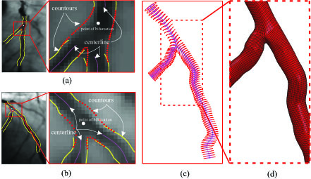
Fig. 1: Image processing: (a-b) enhancement techniques to improve the image quality and segmentation procedure to lumen contours detection applied for the two projected views; (c) 3D coronary vessel modelling: centerline of the branches (blue), outer cross-sections (red) generated from the enlargement of the inner cross-sections (magenta); (d) hexahedral-element mesh of the bifurcated coronary model for the numerical simulations.
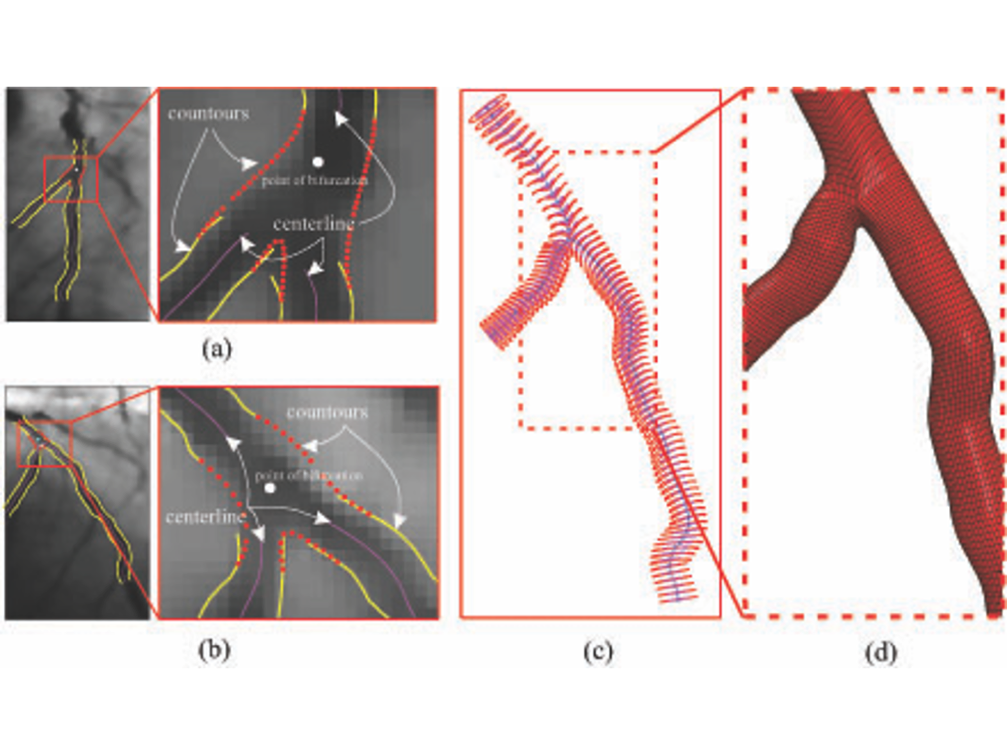
Fig. 1: Image processing: (a-b) enhancement techniques to improve the image quality and segmentation procedure to lumen contours detection applied for the two projected views; (c) 3D coronary vessel modelling: centerline of the branches (blue), outer cross-sections (red) generated from the enlargement of the inner cross-sections (magenta); (d) hexahedral-element mesh of the bifurcated coronary model for the numerical simulations.
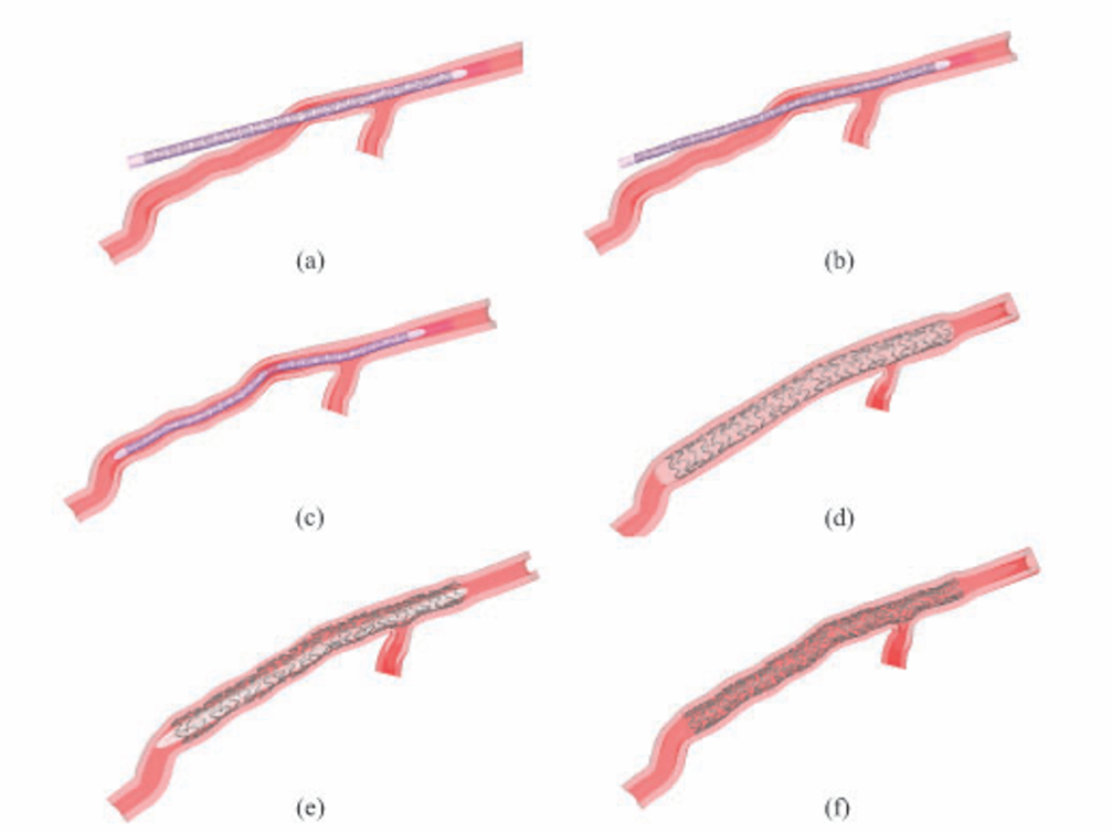
Fig. 2: Stenting procedure of the one long stent: (a) initial configuration; (b) crimping and bending procedure of the stent/balloon through the catheter displacement; (c) final position of the stent/balloon before the balloon inflation; (d) configuration at the maximum balloon expansion (pressure reaches 1.8214 MPa); (e) deflation of the balloon at the pressure of 0 MPa; (f) final configuration of the stent inside the coronary vessel.

Fig. 3: Mapping procedure of two short stents in the distal and proximal part of the coronary artery: (a) initial configuration of the balloon/stent surrounded by the catheter; (b) crimping and bending procedure of the stent/balloon to insert the stent/balloon in the distal region; (c) final position before the balloon expansion; (d) final position of the short stent after the balloon inflation; (e) insertion of the second short stent/balloon in the proximal main vessel after the crimping and bending procedure, like in (b); (f) final position of the second short stent after the balloon expansion.
Conclusions
The results obtained in this study highlighted the critical coronary damage that could be provoked after the two short stents deployment, in particular in the overlapping area.
Main collaborations
- Unità Operativa Complessa (U.O.C.) di Chirurgia d’Urgenza Presidio Ospedaliero S. Eugenio, Dott. G. Sgueglia
Acknowledgements
- Cariplo Foundation through the AVAS_PRO project
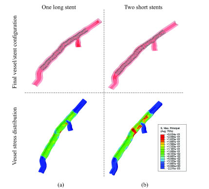
Fig. 4: Comparison of the stress distribution at the end of the stenting procedure: (a) the stenting strategy of one long stent produces an uniform distribution of the stent and remarkable stress results; (b) the application of the two short stents induces a not uniform distribution of the stress and, in particular, the proximal part of the coronary are more stressed than the otherwise.