
Introduction
The widespread acceptance of Carotid Artery Stenting (CAS) to treat a stenosed carotid bifurcation and its effectiveness compared with its surgical counterpart, carotid endarterectomy (CEA) is still a matter of debate [1]. One major concern related to CAS is the possible distal embolization potentially leading to stroke or other severe neurological complications. Embolization is mainly due to the plaque debris and thrombi generated during the dilatation of the stenosis and stent positioning. Consequently embolic protection filters have been developed to capture such released debris and appear to have a significant impact on the success of CAS [2,3]. Currently, several embolic filter designs are available on a rapidly growing dedicated market. However, some drawbacks, such as filtering failure, inability to cross tortuous high-grade stenoses, malpositioning and vessel injury still remain and require further design improvement.
Goal
Complementary to in vitro studies to understand the fluid dynamical behavior of such devices [4], the present study uses the Finite Element Method to investigate some solid mechanical aspects of a commercially available embolic protection filter design. The Finite Element Method was chosen because of its track record in understanding and optimizing the mechanics of cardiovascular devices, such as stents [5].
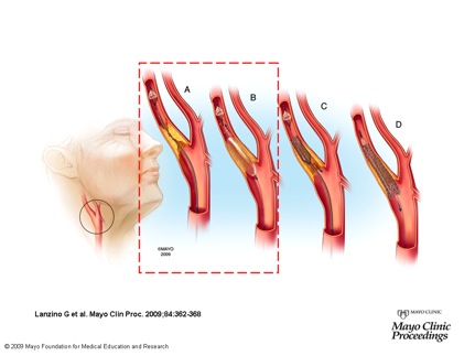
Fig. 1: Carotid Artery Stenting (CAS) procedure; a) through a guidewire an embolc filter is driven above the stenosis and deployed; b) ballon angioplasty is performed to enlarge the stenosis, at this stage some clots can be released and should be captured by the filter; c) deployment of self-expanding Nintinol stent; d) filter retrieval. The RED box highlights the procedure step investigated by Finite Element Analysis (FEA).
Methods
A parametric model of a 4 mm diameter Angioguard embolic filter (Cordis, J&J) was created by means of the open-source pyFormex design software [6]. The model was based on a high resolution microCT scan (see Figure 2-ON LEFT) and the most important model parameters are the number of struts, the percentage of filter coverage and the filter length and diameter. Some design variants are depicted in Figure 2 (ON RIGHT).
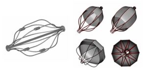
Fig. 2: (ON LEFT) reconstruction of microCT scan of the 4 mm Angioguard filter (membrane not visible); (ON RIGHT) design variants of the Angioguard model: original 4 mm device with 50% membrane coverage (top left), 80% membrane covered 4 mm filter (top right), 8 mm device with 50% membrane coverage (bottom left) and 10 strut variant (bottom right).
Results
The simulation of the filter insertion into the delivery sheath revealed that the basket frame experiences large deformations. The radial compression of the filter frame is accomplished by an axial elongation reducing the diameter from 4 mm to 0.96 mm when the filter is completely inserted into the sheath. A good qualitative agreement is found between the numerical results and the microCT image of the partially deployed Angioguard filter (see Figure 3 (ON LEFT)). The simulations of filter deployment in the straight rigid vessel suggest that, in this case, filter malapposition is caused by inability of the filter struts to accomplish the vessel asymmetry (see Figure 3 (ON LEFT)).
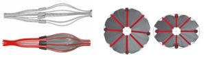
Fig. 3: (ON LEFT) Finite Element simulation (bottom panel) and microCT image (top panel) of partially inserted/released filter into/from the delivery sheath; (ON RIGHT) A 4 mm size filter deployed in a 3 mm circular vessel (on the left) and in 3 mm vessel having 0.75 ovality (on the right).
References
- Furlan A.J., 2006, “Carotid Artery Stenting – Case Open or Closed”, N. Engl. J. Med., 355 (16), pp. 1726-1729.
- Goodney P.P., Schermerhorn M.L. Powell R.J., 2006, “Current Status of Carotid Artery Stenting”, J. Vasc. Surg., 43, pp. 406-411.
- Yen M.H., Lee D.S., Kapadia S., Sachar R., Bhatt D.L., Bajzer C.T., Yadav J.S., 2005, “Symptomatic Patients Have Similar Outcomes compared with Asymptomatic Patients after Carotid Artery Stenting with Emboli Protection”, Am. J. Cardiol., 95, pp. 297-300.
- Siewiorek G.M., Wholey M.H., Finol E.E., 2007, “In Vitro Performance Assessment of Distal Protection Devices for Carotid Artery Stenting: Effect of Physiological Anatomy on Vascular Resistance”, J. Endovasc. Ther., 14 (5), pp. 712-24.
- De Beule M., 2008, “Finite element stent design – Chapter 2.3: Survey of the state of the art in stent modeling”, PhD thesis, Ghent University, Belgium.
- Internet site address: http://pyFormex.berlios.de.
- Internet site address: http://www.abaqus.com .
- Pelton A.R., DiCello J., Miyazaki S., 2000, “Optimization of Processing and Properties Medical Grade Nitinol Wire”, Min. Invas. Ther. & Allied. Tech., 9 (1), pp. 107-118.