Assessing failure’s reason for a SS 316L 3D printed bicycle handlebars
The test has been carried out by B. Rossetti and G. Alaimo using the Litem BYC 200 machine, available at the Department of Civil Engineering and Architecture (DICAR) of Pavia University.
The research activity has been supervised by F. Auricchio.


Figure 1 Experimental set-up
The handlebar was designed according to well-defined criteria of stiffness, weight and yielding resistance.
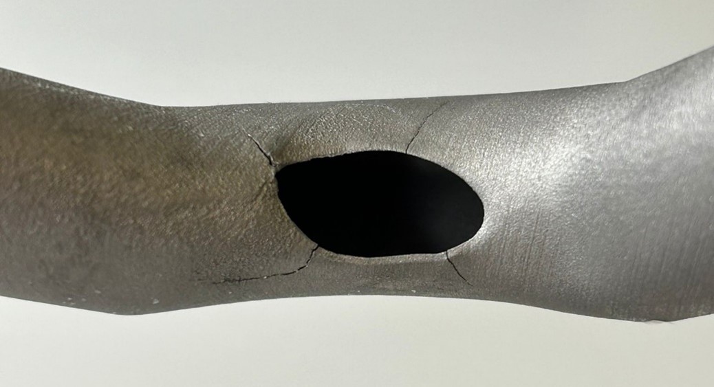
However, during on-road and off-road testing, some cracks were observed near the cable passage hole, as shown in figure 1a. The analysis conducted by UniPV hypothesized that possible causes were fatigue loads, not considered during the design phase. Accordingly, the main goal of this study was to assess the possible causes of failure.

Figure 2a: cracks and fracture surfaces detected during both on-road and off-road testing of the handlebar

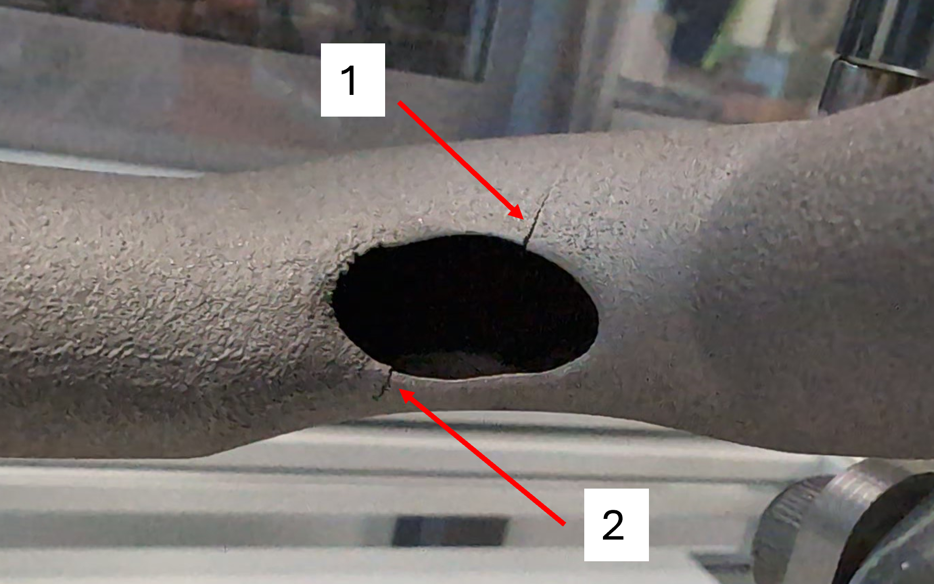
Figure 2b: cracks originated during fatigue test
Figure1: cracks growth comparison between the handlebar used on the road [2a] vs the tested one [2b]
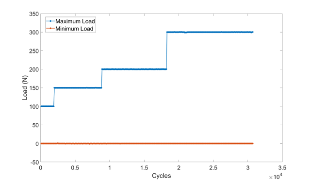
To run the fatigue test, a sinusoidal vertical force was applied on the end of the handlebar, as shown in figure 1. Maximum load was progressively increased throughout the test as illustrated in Figure 3.

Figure 3:maximum and minimum load applied during the test
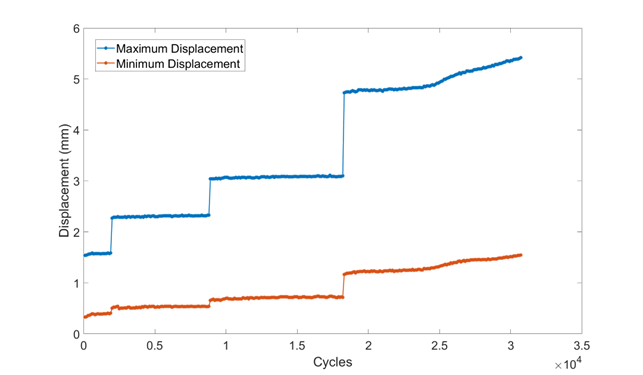
During the test, minimum and maximum displacement values were monitored to assess an eventual crack onset. Results show that the crack marked with label “1” in Figure 2b, happened at about 23200 cycles, as illustrated by the slope variation of maximum displacement presented in figure 4. The second crack, marked with label “2” in figure 2b, has been detected at almost 27000 cycles.

Figure 4: maximum and minimum displacement resulting from load application
The performed fatigue test has validated the original hypothesis that failure of the handlebar originates by fatigue loads not considered during the design stage.

