

Fibre orientation optimisation and experimental validation of a 3D-printed continuos fibre-reinforced composite
Additive manufacturing technologies based on continuous fibre-reinforced composites offer new opportunities for the design of structural components with mechanical properties tailored to specific loading conditions. In particular, the ability to control fibre orientation within individual layers makes it possible to tailor the stiffness and strength of the laminate, enabling the design of structures with mechanical properties suited to the expected loading conditions. In the biomedical field, this approach could contribute to the development of prosthetic components as potential alternatives to conventional metallic solutions. However, the use of continuous fibre-reinforced composites requires accurate mechanical characterization and the development of numerical models capable of predicting their structural response.
Goal: the aim of this study is to assess the ability of a numerical model developed in ANSYS to reproduce the mechanical behaviour of a rhombus-shaped composite structure manufactured by additive manufacturing and subjected to tensile loading. As a preliminary step, numerical simulations were performed to determine the fibre layup configuration that maximises structural stiffness. The selected geometry and layup configuration were then used for an initial experimental-numerical validation, aimed at assessing the model’s ability to reproduce the mechanical response of the component.
Methods: a hollow rhombus-shaped geometry was designed to investigate the mechanical response of an additively manufactured composite component with a more complex, yet regular, shape than conventional tensile test specimens. The component was manufactured using Onyx as the base material, reinforced with continuous carbon fibre. A preliminary numerical analysis was performed in ANSYS Mechanical APDL to identify the fibre layup configuration that maximises the structural stiffness of the component. The specimen was then manufactured using the optimised fibre configuration. The overall orientation of the Onyx and carbon fibre layers, corresponding to the configuration that maximises structural stiffness is shown in Figure 1: the sample consisted of five outer layers made of Onyx and eight inner layers reinforced with continuous carbon fibre, resulting in a total thickness of 2.25 mm.
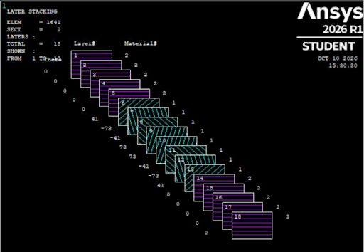
Figure 1: Overall orientation of the Onyx layers (purple) and carbon fibre layers (light blue).
The numerical model of the component was developed in ANSYS Mechanical APDL to simulate its response under tensile loading. The boundary conditions reproduced the experimental configuration: the base of the specimen was constrained, while a displacement was applied in the Y direction to the opposite region.
The component was manufactured using the Markforged X7 3D printer available at ProtoLab, University of Pavia (UNIPV). To accurately represent the manufactured component in the numerical model, the actual material distribution was investigated using the Eiger slicing software. Although each layer included two Onyx perimeters, additional regions of Onyx were also present within the nominally carbon fibre-reinforced layers, reducing the actual amount of carbon fibre incorporated into the specimen. An example of the layer architecture is shown in Figure 2. The actual carbon fibre content was estimated through a detailed analysis of the masses of the materials used during manufacturing. This information was used to quantify the fibre content more accurately and support the definition of the numerical model.
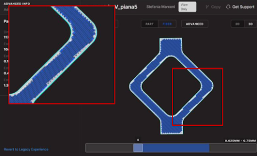
Figure 2: Onyx deposition details (light blue) in a carbon fibre layer.
Figure 3 shows the 3D printed specimen, along with the boundary conditions adopted in both the simulation and the experimental test, with the constrained area highlighted in yellow and the area subjected to displacement in green.
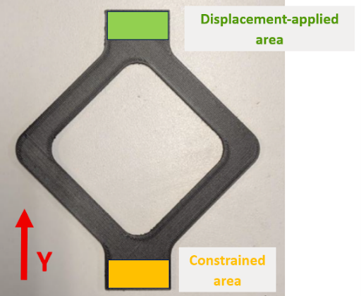
Figure 3: 3D printed rhombus-shaped sample along with the boundaries condition applied in the numerical simulation.
The specimen was subsequently subjected to an experimental tensile test using the LiTem BYC 200 testing machine available at the Department of Civil Engineering and Architecture (DICAR), UNIPV. The test was performed under displacement control at a crosshead speed of 2 mm/min along the Y direction. The experimental set-up is shown in Figure 4. The acquired data were used to obtain the experimental force-displacement curve, which was compared with the numerical response to assess the model’s ability to reproduce the mechanical behaviour of the component.
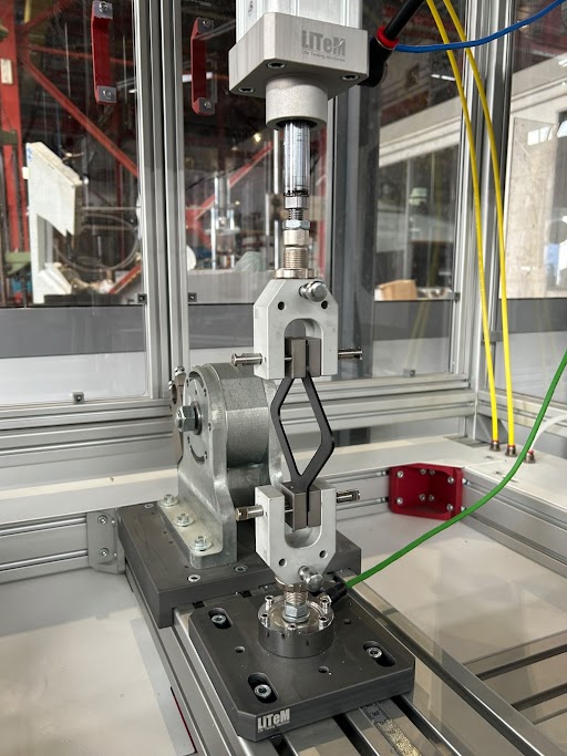
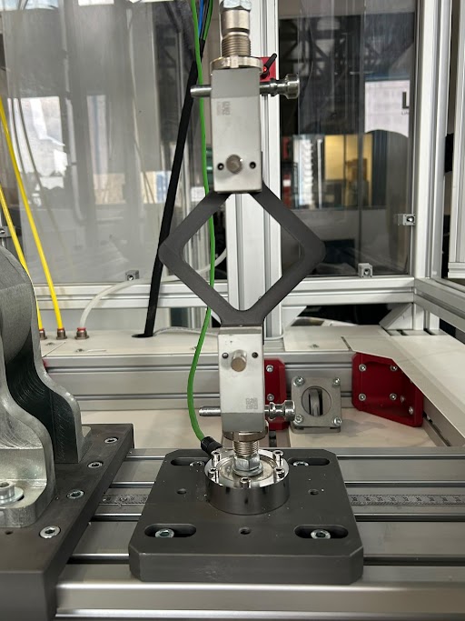
Figure 3: 3D printed rhombus-shaped sample along with the boundaries condition applied in the numerical simulation.
Results: Figure 5 shows the comparison between the experimental and numerical force-displacement data. This comparison makes it possible to assess the accuracy of the numerical model in predicting the structural stiffness and the overall mechanical response of the component. Specifically, the stiffness of the linear portion of the experimental data was found to be 200 N/mm, whereas the corresponding stiffness obtained from the numerical model was 204 N/mm. The agreement between the two curves demonstrates that the developed model can predict the structural stiffness of additively manufactured composite components with high accuracy, even for non-standard geometries and complex fibre orientations. These findings provide a solid basis for the validation of the proposed numerical approach, which will be further assessed on more complex geometries and under different loading conditions.
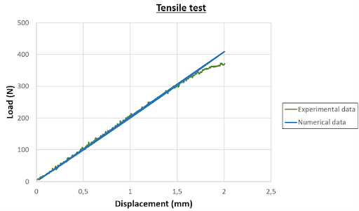
Figure 3: 3D printed rhombus-shaped sample along with the boundaries condition applied in the numerical simulation.
Acknowledgments: the authors would like to thank D. Cagnola for conducting the experimental tensile test, B. Rossetti for supervising the experimental activity, and S. Marconi, G. Alaimo and F. Auricchio for coordinating the research activity.